For a doubly symmetric I-section, I = (B × D³ − (B − tw) × (D − 2tf)³) / 12, and the elastic section modulus is Z = I / (D / 2). For MB 300 this hand formula gives 8870 cm⁴ against the table value of 8990 cm⁴, a 1.3 percent gap that comes from the root radii and tapered flanges the formula ignores.
What I and Z are
The second moment of area, usually called the moment of inertia I, measures how a cross section resists bending. It depends on how far the material sits from the axis of bending, and the distance counts twice, so material far from the axis is worth much more than material near it. That is why a beam is shaped like an I.
The elastic section modulus Z is the moment of inertia divided by the distance from the axis to the extreme fibre. It links a bending moment to the stress at the surface.
Z = I / ystress = M / Z
The rectangle: where everything starts
For a rectangle of width b and depth h, about the axis through its centroid parallel to the width:
I = b × h³ / 12Depth is cubed. Doubling the depth of a rectangular beam makes it eight times stiffer but only twice as heavy. An I-section is a rectangle with the least useful material, the middle, taken out.
The I-section formula
Treat the I-section as a big outer rectangle B × D with two rectangular gaps cut from the sides. Together the gaps are (B − tw) wide and (D − 2tf) deep, so:
I = [ B × D³ − (B − tw) × (D − 2tf)³ ] / 12B is the flange width, D the overall depth, tf the flange thickness and tw the web thickness. The area is A = 2 × B × tf + (D − 2tf) × tw. Both formulas ignore the rounded corners where the web meets the flange, and the slope on the inside face of a rolled beam's flanges.
Checked against MB 300
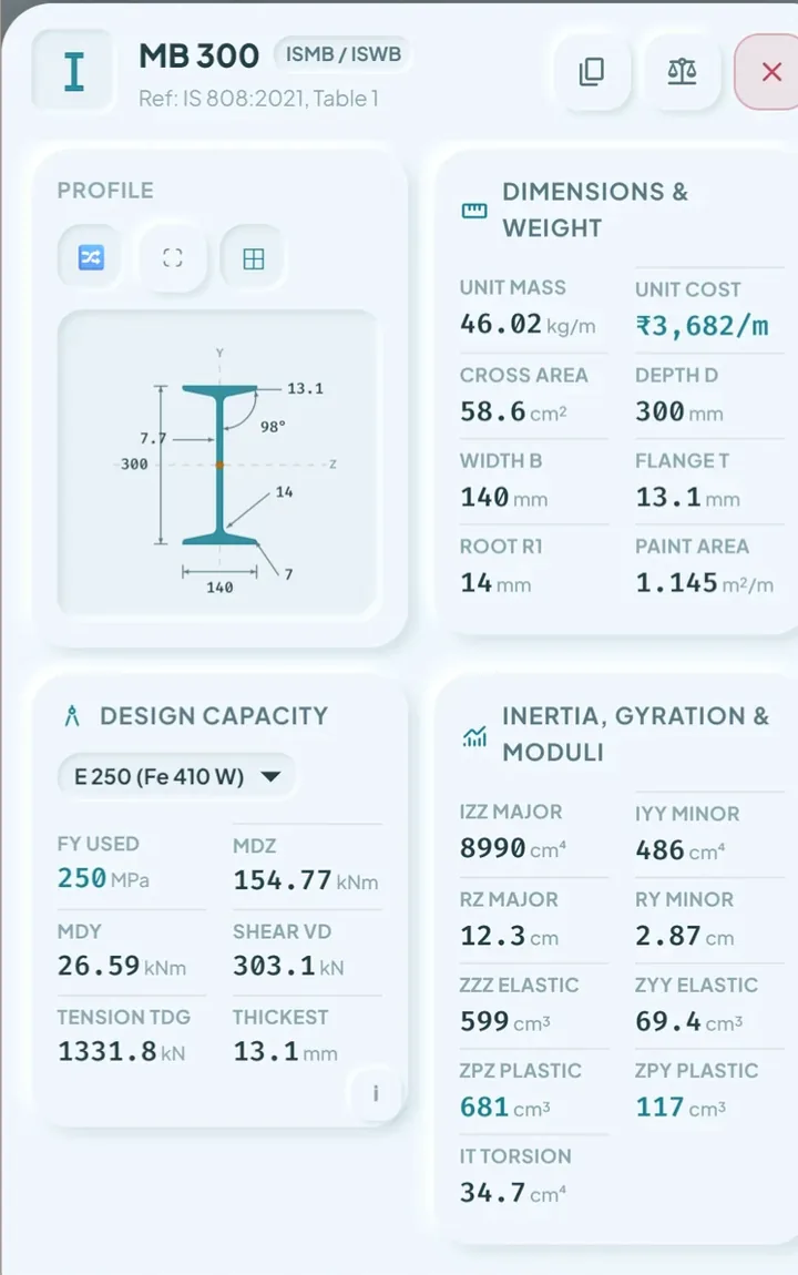
Take the values of MB 300 from IS 808:2021: B = 140 mm, D = 300 mm, tf = 13.1 mm and tw = 7.7 mm.
- D − 2tf = 300 − 26.2 = 273.8 mm
- B × D³ = 140 × 27,000,000 = 3.78 × 10⁹ mm⁴
- (B − tw) × (D − 2tf)³ = 132.3 × 273.8³ = 2.715 × 10⁹ mm⁴
- I = (3.78 − 2.715) × 10⁹ / 12 = 8.87 × 10⁷ mm⁴ = 8870 cm⁴
| Property | Hand formula | IS 808:2021 table | Difference |
|---|---|---|---|
| Area A | 57.76 cm² | 58.6 cm² | 1.4% |
| Izz | 8870 cm⁴ | 8990 cm⁴ | 1.3% |
| Zez = Izz / 150 mm | 591 cm³ | 599 cm³ | 1.3% |
The hand figures are about 1.3 percent low. The root radii add a little material at the web and flange junction, and the sloping flanges are thicker near the web than the listed tf. For learning and for a quick check, the hand formula is good enough. For a design, use the table value, as the guide to reading a section table explains.
A built-up girder and the parallel axis theorem
When a section is made of plates welded together, there is no table. Use the parallel axis theorem: the moment of inertia of each part about the overall axis is its own I plus its area times the square of the distance from its centroid to that axis.
I = Σ ( I own + A × d² )Take a plate girder with a web of 400 × 8 mm and two flange plates of 200 × 16 mm, so the total depth is 432 mm. The flange centroids are 200 + 8 = 208 mm from the axis.
- Web: 8 × 400³ / 12 = 42,666,667 mm⁴
- One flange about its own axis: 200 × 16³ / 12 = 68,267 mm⁴
- One flange transfer term: 3200 × 208² = 138,444,800 mm⁴
- Two flanges: 2 × (68,267 + 138,444,800) = 277,026,133 mm⁴
- Total I = 42,666,667 + 277,026,133 = 319,692,800 mm⁴ = 31,969 cm⁴
The outer-rectangle formula gives the same answer in one line, which makes a useful cross-check: I = (200 × 432³ − 192 × 400³) / 12 = 319,692,800 mm⁴. Both routes agree.
The section modulus is Z = I / (D / 2) = 319,692,800 / 216 = 1,480,059 mm³, which is 1480 cm³. The parallel axis route is the one you need when the parts are not symmetric, for example a girder with unequal flanges, or an I-beam with a cover plate on one side.
Where each number is used
- I goes into deflection, for example δ = 5wL⁴ / (384EI) for a simply supported beam under a uniform load.
- Z goes into bending stress, stress = M / Z, and the elastic moment capacity.
- The plastic modulus Zp goes into the design bending strength of a section that can form a plastic hinge. See the beam capacity guide.
- The radius of gyration, r = √(I / A), goes into column slenderness. See the slenderness guide.
- The target I is what the section optimizer ranks sections against.
Skip the arithmetic
Steel Table India shows Izz, Iyy, the radii of gyration, and the elastic and plastic moduli for every rolled section in the catalogue. For flats and round bars of your own size it computes them live from the geometry. For a built-up girder you still need the parallel axis route above, or a section property calculator.
Questions people ask
What is the formula for the moment of inertia of an I-section?
I = (B × D³ − (B − tw) × (D − 2tf)³) / 12, where B is flange width, D overall depth, tf flange thickness and tw web thickness. It ignores root radii and flange taper.
How do I calculate the section modulus?
Divide the moment of inertia by the distance from the axis to the extreme fibre. For a symmetric section that distance is half the depth, so Z = I / (D / 2).
What is the difference between moment of inertia and section modulus?
Moment of inertia I measures stiffness and goes into deflection. Section modulus Z is I divided by distance to the surface, and it gives the stress for a bending moment.
Why does my hand value differ from the IS 808 table?
The simple formula ignores the root radii and the slope of the flange faces. For MB 300 the hand value is about 1.3 percent lower than the published one.
When do I use the parallel axis theorem?
When a section is built from several parts, such as a plate girder, add each part's own I and its area times the square of the distance from its centroid to the overall axis.
Keep reading
Section properties for every section
Steel Table India lists I, r, Ze and Zp for every IS 808:2021 section. Free on Google Play, works offline.

For reference, not for sign-off. Section and bolt values quoted here are as shown in Steel Table India, transcribed from the published IS 808:2021 tables and worked to IS 800:2007 methods. Transcription can contain errors, and these worked examples make simplifying assumptions stated in the text. Check critical values against the official Bureau of Indian Standards publications and have designs checked by a qualified engineer. IS 808 and IS 800 are published by the Bureau of Indian Standards.