For a bearing-type bolt, design shear strength is φ × Fnv × Ab and design tension strength is φ × Fnt × Ab, with φ = 0.75. A 3/4 in Group 120 (A325 type) bolt with threads in the shear plane carries 17.9 kips in single shear and 29.8 kips in tension. Four of them carry 71.6 kips in shear. Then check the plate: bearing and tearout can govern.
Bolt groups and what the names mean
The RCSC Specification sorts high-strength bolts into groups by minimum tensile strength in ksi. Group 120 is the family that includes ASTM A325 bolts. Group 144 and Group 150 are the higher-strength bolts, which include ASTM A490. Today the A325 and A490 bolts are grades within ASTM F3125, but people still say A325 and A490 on the job, and the old names still help when you read drawings.
The higher groups carry more: in RCSC Table 5.1 the nominal tensile stress is 90 ksi for Group 120, 108 ksi for Group 144 and 113 ksi for Group 150, and the nominal shear stress with threads in the shear plane is 54, 65 and 68 ksi. This guide works Group 120.
Strength depends on two things: the bolt group, which sets the tensile and shear stress, and whether the threads are in the shear plane. Threads cut into the shear area, so a bolt with threads in the plane (called condition N) is weaker in shear than one with the threads excluded (condition X).
| Quantity | Symbol | Value |
|---|---|---|
| Nominal tensile stress | Fnt | 90 ksi |
| Nominal shear stress, threads in shear plane (N) | Fnv | 54 ksi |
| Nominal shear stress, threads excluded (X) | Fnv | 68 ksi |
The area and the stress that matter
The bolt area is the area of the nominal shank. For a 3/4 in bolt:
Ab = π × d² / 4 = π × 0.75² / 4 = 0.4418 in²The nominal strength is stress times area. AISC 360 chapter J gives Fnt and Fnv for each bolt type, and the design strength is that nominal strength times φ = 0.75 for LRFD. For ASD, divide the nominal strength by Ω = 2.00 instead.
Shear strength, worked
Take a single 3/4 in Group 120 bolt, threads in the shear plane, one shear plane:
Rn = Fnv × Ab = 54 × 0.4418 = 23.9 kipsφRn = 0.75 × 23.9 = 17.9 kips
A bolt in double shear has two planes and carries twice that. For a group of four identical bolts in single shear:
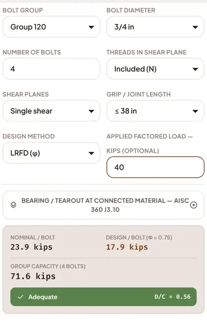
Group strength = 4 × 17.9 = 71.6 kipsThose are the numbers Steel Table USA shows for this case: nominal 23.9 kips per bolt, design 17.9 kips per bolt, and 71.6 kips for four bolts. With an applied factored load of 40 kips the demand-to-capacity ratio is 40 / 71.6 = 0.56, and the app flags the group as adequate.
The joint length also matters. When the distance between the extreme bolts in the line of force is more than 38 in, AISC 360 reduces the bolt shear strength to 83.3 percent of the value above. That is why the calculator asks for the joint length.
Strength per bolt for common sizes
Here are the design strengths of single bolts from 1/2 in to 1-1/4 in. These are Group 120 bolts, bearing-type, LRFD.
| Diameter | Area (in²) | Shear, threads in plane (kips) | Shear, threads excluded (kips) | Tension (kips) |
|---|---|---|---|---|
| 1/2 in | 0.1963 | 8.0 | 10.0 | 13.3 |
| 5/8 in | 0.3068 | 12.4 | 15.6 | 20.7 |
| 3/4 in | 0.4418 | 17.9 | 22.5 | 29.8 |
| 7/8 in | 0.6013 | 24.4 | 30.7 | 40.6 |
| 1 in | 0.7854 | 31.8 | 40.1 | 53.0 |
| 1-1/8 in | 0.9940 | 40.3 | 50.7 | 67.1 |
| 1-1/4 in | 1.2272 | 49.7 | 62.6 | 82.8 |
The jump from threads included to excluded is the ratio 68 / 54, about 26 percent. If the threads can be kept out of the shear plane, and the detail is checked in the field, you get that strength back.
Tension and combined tension and shear
For a bolt in pure tension:
φRn = 0.75 × Fnt × Ab = 0.75 × 90 × 0.4418 = 29.8 kips (3/4 in)When a bolt carries shear and tension together, as in a bracket connection, the tension strength is reduced by the shear stress already in the bolt. AISC 360 section J3.7 for bearing-type connections gives a reduced tensile stress:
F′nt = 1.3 Fnt − (Fnt / (φ Fnv)) × frv but not more than FntHere frv is the required shear stress in the bolt. Suppose each 3/4 in bolt carries 10 kips of shear:
- frv = 10 / 0.4418 = 22.6 ksi, which is below φFnv = 40.5 ksi, so the shear alone is fine.
- F′nt = 1.3 × 90 − (90 / (0.75 × 54)) × 22.6 = 66.7 ksi.
- φRn in tension = 0.75 × 66.7 × 0.4418 = 22.1 kips.
So a bolt that is also carrying 10 kips of shear can take about 22.1 kips of tension, compared with 29.8 kips with no shear. Prying action can add to the tension in the bolt, so for a flexible connection detail check it too.
Bearing and tearout at the plate
The bolt is only half the joint. The plate it bears on can fail first. For bolts in standard holes where the deformation around the hole is a design consideration, the bearing and tearout strength of one bolt is, from AISC 360 section J3.10:
Rn = 1.2 × Lc × t × Fu but not more than 2.4 × d × t × Fu φ = 0.75Lc is the clear distance in the direction of the force from the edge of the hole to the edge of the plate, or to the edge of the next hole. Say the plate is 3/8 in A36 steel (Fu = 58 ksi) and the bolt center is 1.25 in from the edge. A standard hole for a 3/4 in bolt is 13/16 in.
- Lc = 1.25 − (13/16) / 2 = 0.844 in.
- Tearout limit: 1.2 × 0.844 × 0.375 × 58 = 22.0 kips.
- Bearing cap: 2.4 × 0.75 × 0.375 × 58 = 39.1 kips.
- Tearout is smaller, so φRn = 0.75 × 22.0 = 16.5 kips per bolt.
The plate gives 16.5 kips per bolt and the bolt gives 17.9 kips, so the plate governs this joint. The calculator has an optional bearing and tearout check for exactly this reason.
When the joint must not slip
In a bearing-type joint, the bolts slide a little until they bear on the holes. In a slip-critical joint, the bolts are tightened to a minimum pretension and the clamping force holds the plates by friction, so the joint does not slip under service load. Slip-critical design uses a different formula, based on the pretension, the surface class and the hole type. The hole size and pretension chart lists the numbers and works a slip resistance example.
Slips to avoid
- Mixing up N and X. Assuming threads are excluded when they are not overstates shear strength by about 26 percent.
- Forgetting the second shear plane. Count the planes the bolt crosses, not the plates.
- Checking the bolts and not the plate. Bearing, tearout, block shear and net section of the connected part can all govern.
- Using nominal strength as design strength. The 23.9 kips is nominal. The design value is 17.9 kips.
- Ignoring long joints. Over 38 in between extreme bolts, shear strength drops to 83.3 percent.
Check it in Bolt Mode
Flip the switch at the top of Steel Table USA to Bolt Mode and scroll to the Bolt Group Calculator. Choose bearing-type or slip-critical, then the bolt group and diameter. Set the number of bolts, the number of shear planes and whether threads are in the plane. Pick LRFD or ASD, and optionally type your applied load. The calculator shows capacity per bolt and for the group, in kips, and flags the group as adequate or overstressed. Turn on the bearing and tearout check to include the connected plate.
The calculator is built on the RCSC and AISC 360 data in the app, and the results above match it. If the bolt group is part of a bigger check, see how to check a beam to AISC 360.
Questions people ask
What is the shear capacity of a 3/4 inch A325 bolt?
In single shear with threads in the shear plane, the nominal strength is 23.9 kips and the LRFD design strength is 17.9 kips. With threads excluded it is 22.5 kips.
What is the tension capacity of a 3/4 inch A325 bolt?
The LRFD design tensile strength is 0.75 × 90 ksi × 0.4418 in² = 29.8 kips, before any reduction for shear or prying.
What does Group 120 mean for bolts?
It is the RCSC grouping of high-strength bolts with a 120 ksi minimum tensile strength. It includes ASTM A325 bolts. Groups 144 and 150 are the higher-strength bolts, which include A490.
What is the difference between N and X for bolt shear?
N means the threads are in the shear plane and X means they are excluded from it. X has a higher nominal shear stress, 68 ksi against 54 ksi for Group 120, because the full shank carries the shear.
How do I check bolt bearing and tearout?
Use AISC 360 section J3.10. The strength per bolt is 1.2 Lc t Fu, limited to 2.4 d t Fu, with φ = 0.75. Lc is the clear distance to the edge or the next hole.
Can I use these results as a complete connection design?
No. A complete connection also needs block shear, net section, weld checks, prying, edge and spacing rules and slip resistance where required. It should be checked by a licensed engineer.
Keep reading
Bolt group capacity, one screen
Steel Table USA includes RCSC tables and a bolt group calculator in Bolt Mode. Free on Google Play, works offline.

For reference, not for sign-off. Shape and bolt values quoted here are as shown in Steel Table USA, which takes rolled shape data from the AISC Shapes Database v16.0 and bolt tables from the RCSC Specification (2020), and the worked examples follow AISC 360 methods under the simplifying assumptions stated in the text. Transcription can contain errors. Check critical values against the AISC Steel Construction Manual and the RCSC Specification, and have designs checked by a licensed engineer. The AISC Specification, Manual and Shapes Database are published by the American Institute of Steel Construction, and the RCSC Specification by the Research Council on Structural Connections. Steel Table USA is an independent app and is not affiliated with or endorsed by either organization.