For a compact W-shape that is fully braced, the LRFD design strengths are short formulas. Bending: φMn = 0.90 × Fy × Zx. Shear: φVn = φ × 0.6 × Fy × d × tw. Tension yielding: φTn = 0.90 × Fy × Ag. For W12x26 in A992 steel (Fy = 50 ksi) bending is about 139.5 kip-ft, tension is about 344 kips and shear is 75.8 to 84.2 kips depending on the φ used.
What a design strength is
AISC 360 gives two ways to check a member, LRFD (load and resistance factor design) and ASD (allowable strength design). This guide uses LRFD. You work out the force the member must carry using factored loads, and you work out the strength it can provide: the nominal strength times a resistance factor φ. The member passes when the required force is no larger than the design strength.
The steel in a W-shape is usually ASTM A992, with a minimum yield stress Fy of 50 ksi. That is the value used here. For A36 steel, Fy is 36 ksi, and every strength below scales with it.
The numbers you take from the shape table
Everything below comes from one row of the AISC Shapes Database, the W12x26. If you want to know what each symbol means, the guide to reading a shape table covers them.
| Symbol | Meaning | Value |
|---|---|---|
| Zx | Plastic section modulus, strong axis | 37.2 in³ |
| Zy | Plastic section modulus, weak axis | 8.17 in³ |
| A | Cross-section area | 7.65 in² |
| d | Overall depth | 12.2 in |
| tw | Web thickness | 0.230 in |
| bf, tf | Flange width and thickness | 6.49 in, 0.380 in |
| Ix | Moment of inertia, strong axis | 204 in⁴ |
| ry | Radius of gyration, weak axis | 1.51 in |
Moments in these formulas come out in kip-inches. Divide by 12 to get kip-feet. One kip is 1,000 pounds.
Is the shape compact?
The simple bending formula below holds for compact shapes, where the flange and web are stocky enough to reach full plastic strength before they buckle locally. Two ratios decide it, checked against limits from AISC 360 Table B4.1b for flexure.
- Flange: bf / 2tf = 6.49 / (2 × 0.380) = 8.54. The compact limit is 0.38 √(E / Fy) = 9.15 for Fy = 50 ksi. 8.54 is below it.
- Web: h / tw = 47.1, using h = d − 2k. The compact limit is 3.76 √(E / Fy) = 90.6. 47.1 is well below it.
W12x26 is compact in A992 steel, so the full plastic moment is available, provided the beam does not buckle sideways.
Bending strength
For a compact I-shape braced so that its compression flange cannot move sideways, yielding governs and the nominal strength is the plastic moment:
Mn = Fy × Zx φb = 0.90For bending about the strong axis of W12x26:
φMn = 0.90 × 50 × 37.2 = 1,674 kip-in = 139.5 kip-ftAbout the weak axis, the same formula with Zy gives:
φMny = 0.90 × 50 × 8.17 = 367.7 kip-in = 30.6 kip-ftSteel Table USA shows 139.70 kip-ft and 30.69 kip-ft. The last digit differs because the app uses the unrounded values in the database and the table above is rounded to three figures.
Lateral-torsional buckling: the assumption behind the number
The 139.5 kip-ft figure is an upper bound. It assumes the compression flange is braced often enough that the beam cannot twist and bend sideways. The distance within which that holds is the limiting unbraced length Lp:
Lp = 1.76 × ry × √(E / Fy) = 1.76 × 1.51 × √(29,000 / 50) = 64.0 in = 5.3 ftIf W12x26 is braced at intervals of about 5.3 ft or less, for example by a steel deck welded to the top flange, the plastic moment applies. If the unbraced length is longer, AISC 360 section F2 reduces the strength, and the reduction can be large for a long span with no bracing.
Shear strength
The web carries the shear. For rolled I-shapes the shear area is the overall depth times the web thickness, and the nominal strength is:
Vn = 0.6 × Fy × Aw × Cv1 Aw = d × twFor W12x26, Aw = 12.2 × 0.230 = 2.806 in². The web is stocky enough that Cv1 = 1.0, so:
Vn = 0.6 × 50 × 2.806 = 84.2 kipsNow the resistance factor. AISC 360-16 lets you use φv = 1.00 for the webs of rolled I-shapes whose h / tw is within 2.24 √(E / Fy) = 53.9, which W12x26 meets with h / tw = 47.1. That gives φVn = 84.2 kips. If you take the more conservative φ = 0.90 you get 75.8 kips, which is the 75.8 kips Steel Table USA displays. The app errs on the safe side. Check which factor your project and your reviewer expect.
If a beam has high shear and high moment at the same location, there is no interaction reduction for the usual rolled I-shape in AISC 360. The shear is checked on its own, and in most simply supported beams the largest shear sits at the supports where the moment is small.
Tension strength
For direct tension, the yielding limit of the gross section is:
φTn = 0.90 × Fy × Ag = 0.90 × 50 × 7.65 = 344.2 kipsThis is the yielding check only. In a real tension member connected with bolts, rupture of the net section and block shear at the connection often govern and give smaller values. Check them whenever bolt holes are present. The guide to bolt capacity covers the bolt side of that connection.
Deflection, a separate check
Strength and deflection are different checks. Deflection is a serviceability check under service loads and it uses the moment of inertia, not the section modulus. For a simply supported beam under a uniform service load w over a span L:
δ = 5 × w × L⁴ / (384 × E × I)E for steel is 29,000 ksi. Take an illustrative case: W12x26 over a 20 ft span carrying 1.0 kip/ft of service load. In kips and inches, w = 1.0 / 12 = 0.0833 kip/in, L = 240 in and I = 204 in⁴:
δ = 5 × 0.0833 × 240⁴ / (384 × 29,000 × 204) = 0.61 inThat is L / 394. The limit you compare against depends on what the beam supports and which code governs. Many floor beams are held to L/360 under live load. Look up the limit that applies to your case.
Results in one table
| Check | Formula | Result |
|---|---|---|
| Bending, strong axis | 0.90 Fy Zx | 139.5 kip-ft |
| Bending, weak axis | 0.90 Fy Zy | 30.6 kip-ft |
| Shear, φ = 1.00 | 0.6 Fy d tw | 84.2 kips |
| Shear, φ = 0.90 | 0.9 × 0.6 Fy d tw | 75.8 kips |
| Tension, gross yielding | 0.90 Fy Ag | 344.2 kips |
| Deflection, 20 ft span, 1.0 kip/ft | 5wL⁴ / 384EI | 0.61 in |
What these numbers do not cover
A shape strength table is a starting point, not a finished design. These checks still need doing for a real beam:
- Lateral-torsional buckling when the unbraced length is longer than Lp.
- Local buckling for shapes that are not compact.
- Web yielding and web crippling at supports and under concentrated loads.
- Combined bending and axial load for beam-columns.
- Connections, including bolts, welds, block shear and the net section of the member.
- Load combinations and the load factors that produce the required strength.
Check it on your phone
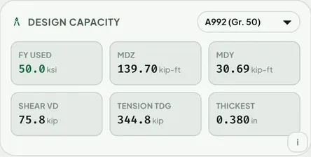
Steel Table USA works out these strengths for every shape in the catalogue. Open any shape, pick a steel grade such as A36 or A992 from the dropdown, and the Design Capacity card in the Inspect panel lists Fy used, the strong and weak axis bending strengths, shear and tension. For W12x26 in A992 the card shows 139.70 kip-ft, 30.69 kip-ft, 75.8 kips and 344.8 kips. The small i button on the card lists the assumptions, including full lateral support.
If a beam fails, the Optimizer ranks lighter or stiffer alternatives, which the guide to picking the lightest section explains. To go from a span and a load to a size, see What size steel beam do I need for a span?
Questions people ask
What is the design bending strength of a W12x26?
In A992 steel with Fy = 50 ksi, φMn = 0.90 × 50 × 37.2 ÷ 12 = 139.5 kip-ft, assuming the beam is compact and braced at intervals no longer than about 5.3 ft.
What resistance factor does AISC 360 use for bending?
φb = 0.90 for LRFD. For ASD the safety factor is Ωb = 1.67.
How do I calculate the shear capacity of a steel beam?
Take the shear area as depth times web thickness and apply Vn = 0.6 Fy Aw Cv1. For W12x26 that is 84.2 kips nominal, and φVn is 84.2 kips with φ = 1.00 or 75.8 kips with φ = 0.90.
What is the difference between A36 and A992 for a beam?
The yield stress. A36 has Fy = 36 ksi and A992 has Fy = 50 ksi, so the same W-shape has about 39 percent more bending strength in A992. Wide-flange shapes are normally specified as A992.
Why is my hand calculation different from the app?
The usual causes are the number of digits in the section properties, a different resistance factor for shear, a different steel grade, or a different assumption about lateral bracing or compactness. Confirm that both calculations make the same assumptions.
Can I use these results as a complete beam design?
No. They are section strengths. A complete design also needs lateral-torsional buckling, web checks, connections and load combinations, and it should be checked by a licensed engineer.
Keep reading
AISC 360 strengths, one tap
Steel Table USA shows design capacity for every shape in the AISC Shapes Database. Free on Google Play, works offline.

For reference, not for sign-off. Shape and bolt values quoted here are as shown in Steel Table USA, which takes rolled shape data from the AISC Shapes Database v16.0 and bolt tables from the RCSC Specification (2020), and the worked examples follow AISC 360 methods under the simplifying assumptions stated in the text. Transcription can contain errors. Check critical values against the AISC Steel Construction Manual and the RCSC Specification, and have designs checked by a licensed engineer. The AISC Specification, Manual and Shapes Database are published by the American Institute of Steel Construction, and the RCSC Specification by the Research Council on Structural Connections. Steel Table USA is an independent app and is not affiliated with or endorsed by either organization.