Work out the factored moment Mu = wuL²/8, then the plastic modulus you need, Zx = Mu / (0.90 Fy), then check deflection with Ix. For a 20 ft span carrying 0.6 kip/ft dead and 0.8 kip/ft live load, Mu is 100 kip-ft, Zx required is 26.7 in³, and a W14x22 works. As a rough rule, the beam depth in inches is about the span in feet divided by 2.
The method in five steps
For a simply supported beam under a uniform load, using LRFD with A992 steel (Fy = 50 ksi):
- Factor the load. wu = 1.2 × dead + 1.6 × live, in kip/ft. Include the beam's own weight in the dead load.
- Find the moment. Mu = wu L² / 8, in kip-ft, with L in feet.
- Find the plastic modulus needed. Zx,req = Mu × 12 / (0.90 × Fy), in in³. Choose a shape with Zx at least that big.
- Check shear. Vu = wu L / 2 against φVn. Shear rarely governs for ordinary spans.
- Check deflection. Find the Ix needed from I = 5wL⁴ / (384 E δ) twice: with the service live load and a limit such as L/360, and with the total service load and L/240. Use the larger.
The strength formulas come from AISC 360 and are explained in how to check a beam to AISC 360.
Worked example: 20 ft span
A floor beam spans 20 ft. Dead load, including the beam weight, is 0.6 kip/ft. Live load is 0.8 kip/ft. The beam is fully braced by the floor deck.
- wu = 1.2 × 0.6 + 1.6 × 0.8 = 2.00 kip/ft
- Mu = 2.00 × 20² / 8 = 100 kip-ft
- Zx,req = 100 × 12 / (0.90 × 50) = 26.7 in³
- Vu = 2.00 × 20 / 2 = 20 kips, which any of the candidates below covers.
- Live load deflection, limit L/360 = 240 / 360 = 0.667 in: Ireq = 5 × (0.8 / 12) × 240⁴ / (384 × 29,000 × 0.667) = 149 in⁴
- Total load deflection, limit L/240 = 1.000 in: Ireq = 5 × (1.4 / 12) × 240⁴ / (384 × 29,000 × 1.000) = 174 in⁴. This is the larger of the two, so it governs.
Candidates that pass
These are the lightest shapes with Zx of at least 26.7 in³ and Ix of at least 174 in⁴, and compact so the plastic moment is available. The W12x22 has the same weight as the W14x22 but only 156 in⁴, so it fails the total load deflection check.
| Shape | Weight (lb/ft) | Zx (in³) | Ix (in⁴) | φMn (kip-ft) |
|---|---|---|---|---|
| W14x22 | 22 | 33.2 | 199 | 124.5 |
| W16x26 | 26 | 44.2 | 301 | 165.8 |
| W14x26 | 26 | 40.2 | 245 | 150.8 |
| W12x26 | 26 | 37.2 | 204 | 139.5 |
| W14x30 | 30 | 47.3 | 291 | 177.4 |
| W12x30 | 30 | 43.1 | 238 | 161.6 |
The W14x22 is the lightest that passes. It has 124.5 kip-ft of bending strength against 100 needed, so deflection, not strength, is what chose it. The W12x26 is shallower, which may matter if headroom is tight, and it is a common shape that is sometimes cheaper to buy. Beam weight was assumed in the dead load, so confirm that 22 lb/ft is consistent with what you allowed.
Span table: lightest W-shape
This table runs the same method for common spans and total service loads. It gives the lightest shape that passes, not the one you must use.
| Span | 0.5 kip/ft | 1.0 kip/ft | 2.0 kip/ft | 3.0 kip/ft | 4.0 kip/ft |
|---|---|---|---|---|---|
| 10 ft | W6x12 | W6x12 | W8x13 | W12x14 | W12x16 |
| 12 ft | W6x12 | W8x13 | W12x14 | W12x19 | W14x22 |
| 16 ft | W8x13 | W12x14 | W12x19 | W16x26 | W16x31 |
| 20 ft | W12x14 | W12x19 | W16x26 | W18x35 | W18x40 |
| 24 ft | W12x19 | W16x26 | W18x35 | W21x44 | W21x50 |
| 30 ft | W16x26 | W18x35 | W21x44 | W24x55 | W24x68 |
For a quick read: a 20 ft span carrying 2 kip/ft needs about a W16x26. The same load over 30 ft needs a W24x55, more than double the weight, because moment grows with the square of the span.
What the table assumes
- Simply supported span, uniform load, A992 steel with Fy = 50 ksi.
- The load is the total service load in kip/ft, split equally between dead and live, so wu = 1.2 × 0.5 w + 1.6 × 0.5 w = 1.4 w. The beam's own weight is inside that load.
- Full lateral support, so lateral-torsional buckling does not reduce strength.
- Compact shapes only, with bending strength 0.90 Fy Zx and shear with the AISC 360 resistance factor.
- Deflection limits of L/360 under the live half and L/240 under total load, whichever is stricter.
- Shapes lighter than 10 lb/ft are left out.
The depth rule of thumb
Before any calculation, a floor beam is often started at a depth in inches of about half the span in feet. A 20 ft span suggests a 10 in deep beam, and a 24 ft span suggests 12 in. The table shows why it works as a first guess and why it is only that: the 20 ft, 2 kip/ft beam is a W16, deeper than the rule suggests, because that load is heavy. Use the rule to start, and the method above to confirm.
What still needs checking
- Lateral bracing. Without a deck or bracing, bending strength drops. See Lp in the beam capacity guide.
- Concentrated loads, which change the moment diagram.
- Web yielding and crippling at supports and load points.
- Connections and bearing length.
- Vibration, for floors with long spans and light loads.
- The loads and combinations your code requires. The ones in this guide are illustrative.
Look up and compare the candidates
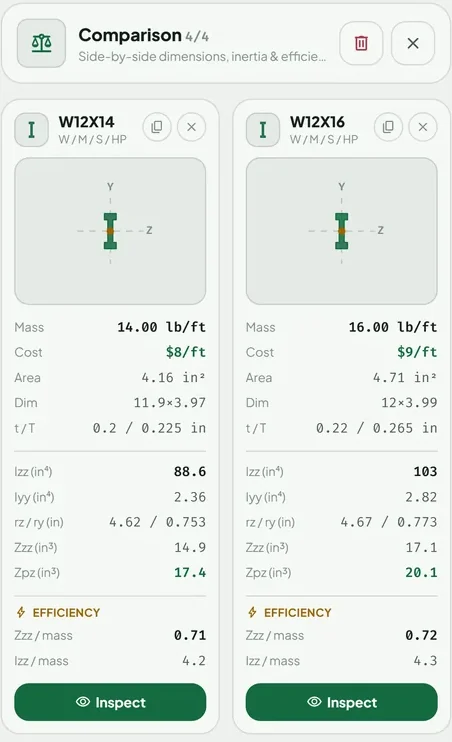
Once you have a few shapes, open them in Steel Table USA. Inspect shows I, S and Z, and the Design Capacity card gives bending, shear and tension for A992. Add up to four shapes to Compare and look at weight, cost per foot and section properties side by side. If you only know the required I, the Optimizer ranks shapes by weight. See how to pick the lightest section.
Questions people ask
What size steel beam do I need for a 20 foot span?
It depends on the load. For 0.6 kip/ft dead and 0.8 kip/ft live, a W14x22 is enough for strength and deflection, assuming full lateral support. A heavier load of 2 kip/ft total needs about a W16x26.
How do I calculate the beam size for a given load?
Find Mu = wuL²/8, then Zx required = Mu × 12 / (0.90 Fy), choose a W-shape with at least that Zx, then check shear and deflection.
What is a rule of thumb for beam depth?
About the span in feet divided by 2 gives the depth in inches, so a 20 ft span starts at about a 10 in deep beam. It is only a first guess.
What does lateral bracing do for a steel beam?
It stops the compression flange from buckling sideways, so the beam can reach its full plastic moment. A floor deck welded to the top flange usually provides it.
Which deflection limit should I use?
Many floor beams use L/360 for live load and L/240 for total load. Your code and the finishes the beam supports set the real limit.
Can I use this table for a real project?
No. It is a planning aid with stated assumptions. A real beam needs the loads and combinations your code requires, bracing, connection and web checks, and review by a licensed engineer.
Keep reading
Compare the candidates
Look up weight, cost and design capacity of any W-shape in Steel Table USA. Free on Google Play, works offline.

For reference, not for sign-off. Shape and bolt values quoted here are as shown in Steel Table USA, which takes rolled shape data from the AISC Shapes Database v16.0 and bolt tables from the RCSC Specification (2020), and the worked examples follow AISC 360 methods under the simplifying assumptions stated in the text. Transcription can contain errors. Check critical values against the AISC Steel Construction Manual and the RCSC Specification, and have designs checked by a licensed engineer. The AISC Specification, Manual and Shapes Database are published by the American Institute of Steel Construction, and the RCSC Specification by the Research Council on Structural Connections. Steel Table USA is an independent app and is not affiliated with or endorsed by either organization.